This week I began the construction of the MTM Snap.
I started with the dxf file posted by Jonathan Ward on the design page and began the process of creating a local copy for our lab.
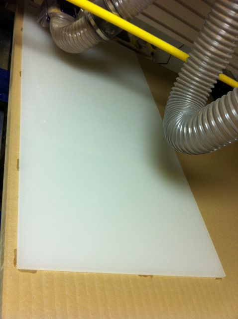
I used 1/2" HDPE from McMaster Carr per the BOM.
I began by resurfaced table, the existing spoil board had become uneven. I then verified the x-y squareness by measuring the diagonals of a machined 94"x44" rect which were within 1/16".
There was some play in the x axis movement and I tightened the mesh between the 2 x-axis motor pinion gears and the corresponding racks mounted on hte rails of the bed.
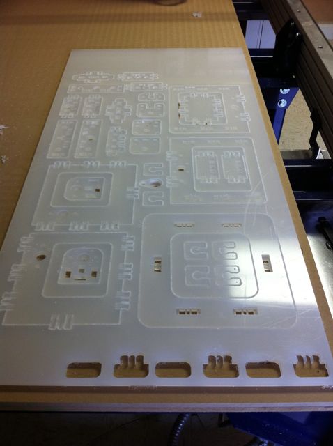
The HDPE sheet was mounted to the table with hot melt glue.
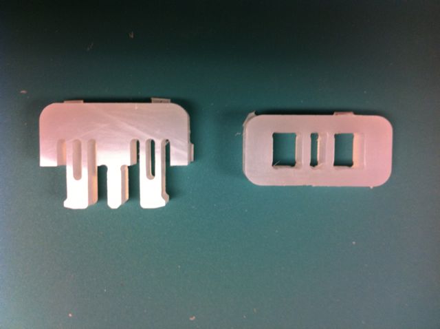
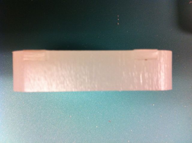
Cut two snap connectors as a test - one conventionl and one climb. The conventional mill had much better surface finish. I produced the initial parts with .125" tabs which proved difficult to remove and appeared to be more then was needed. I produced another snap connector with .0625" tabs and that worked very well.

Created tools in partworks for the 3.1mm drill and the 1/8" end mill establishing the speeds and feedrates appropriate to the job as specified by Jonathan on the design page.
Produced tool paths for each functional layer of the dxf file.
Paths were generated for drill, 1/8" pocket, 1/4" pocket, 3/8" pocket, inside profile cutout, and outside profile cutout. They were machined in that order.
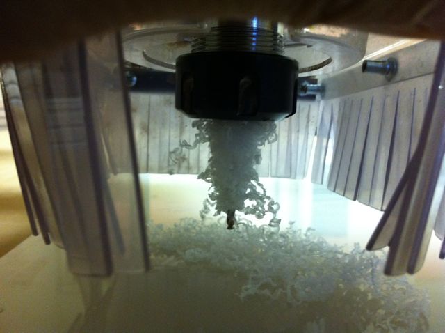
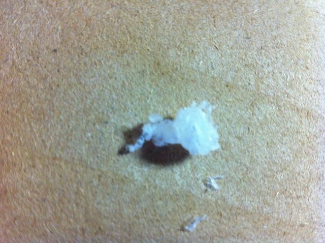
During drilling and pocket milling plastic accumulation on the bit occured and produced some surface burning . After noticing it as the tool moved from a machining position I began monitoring the cutting process with a flashlight as the contrast with the white plastic is low. I stopped several times and cleared the bits to prevent further damage to the parts.
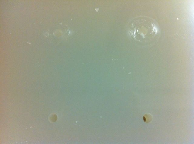
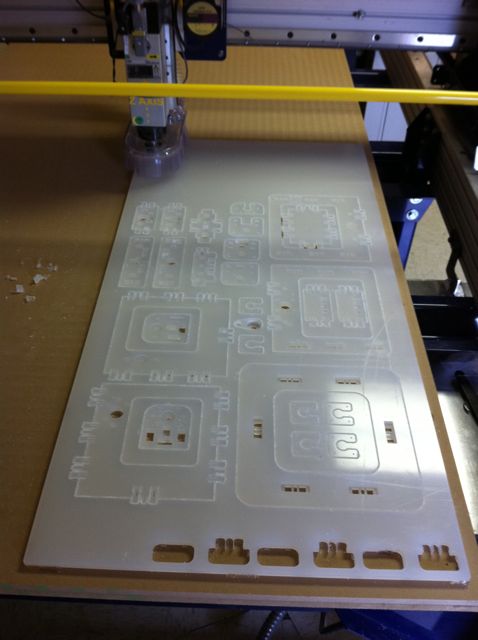
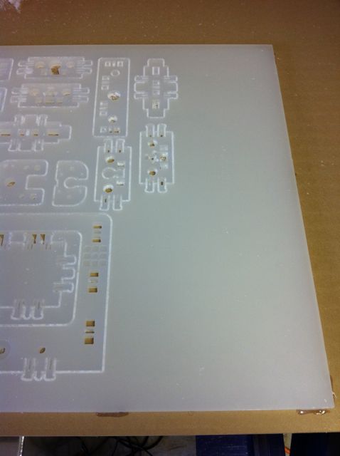
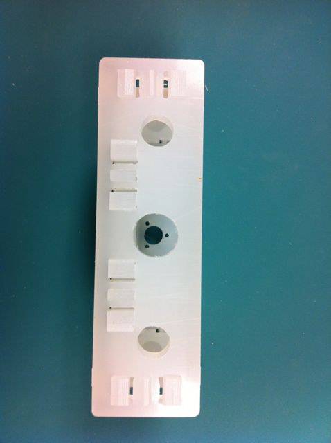
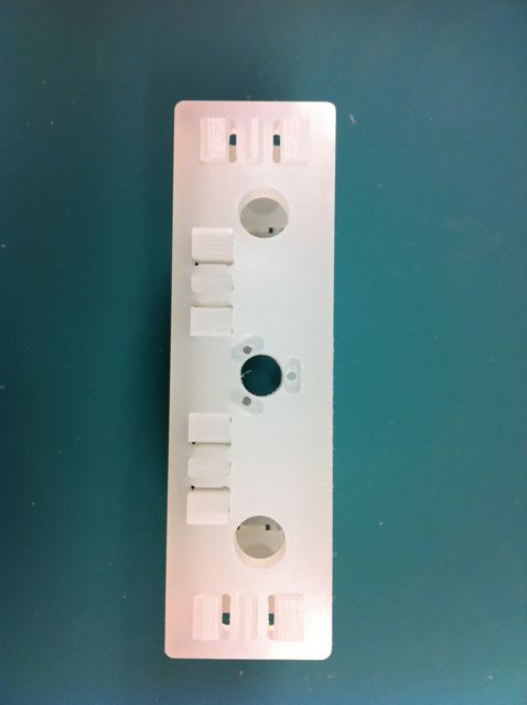
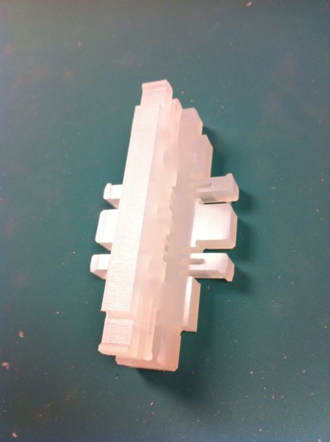
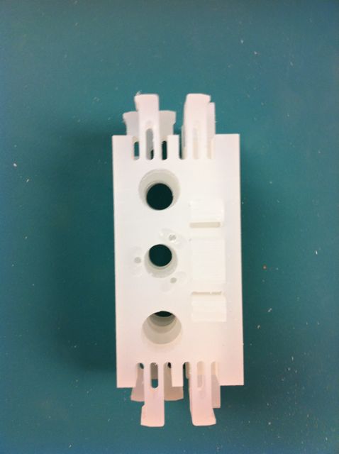
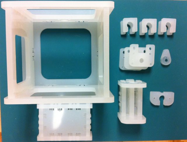
Set of parts produced still in sheet.
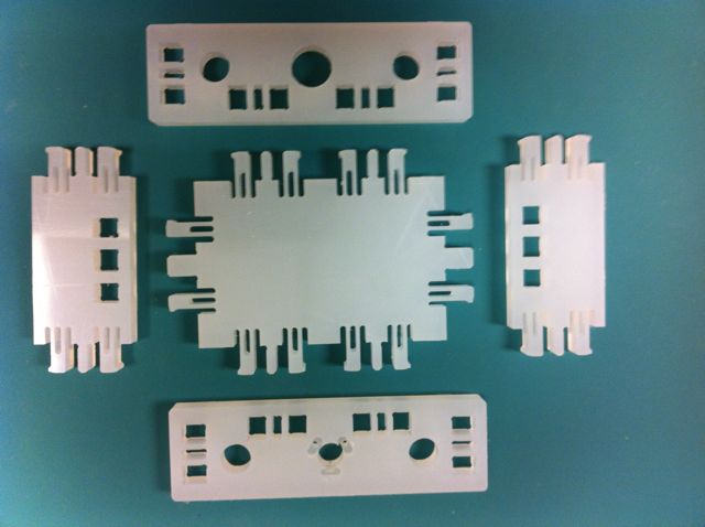
Made replacement pieces for 4 parts that were marred by burning from accumulated plastic on the end mill. The deformation from the drill were not serious enough to require rework.
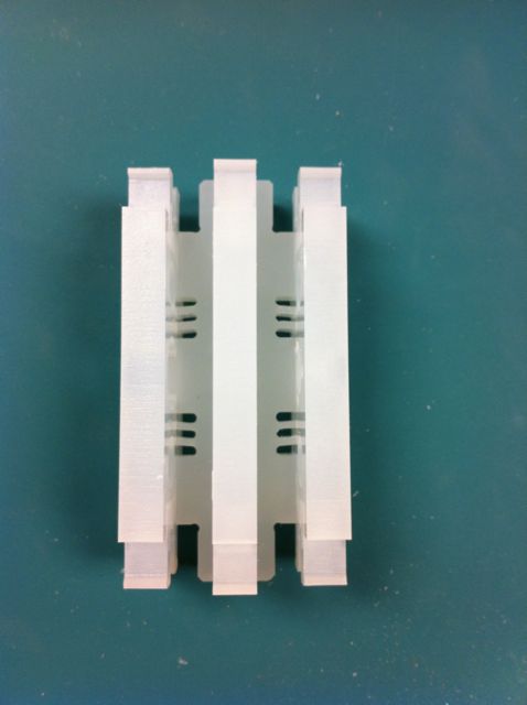
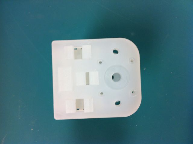
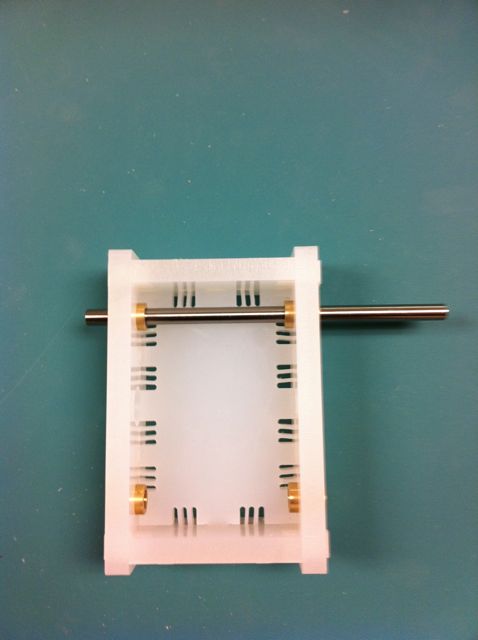
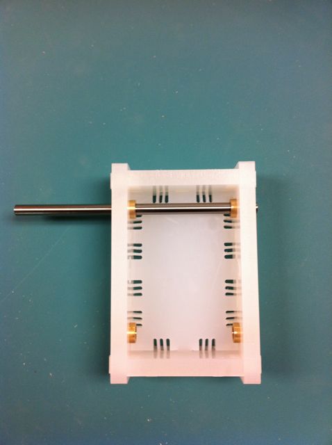
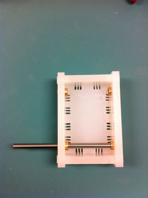
Table
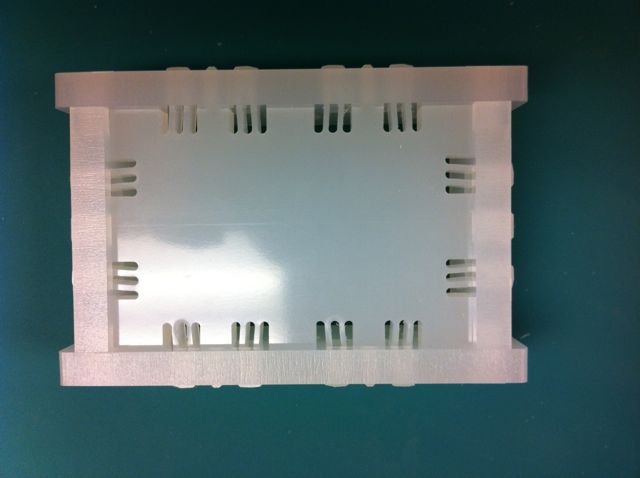
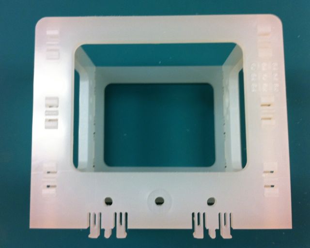
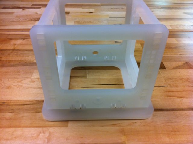
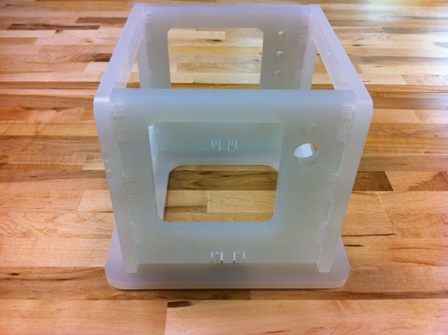
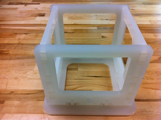
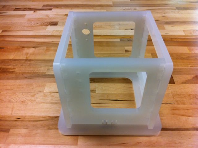
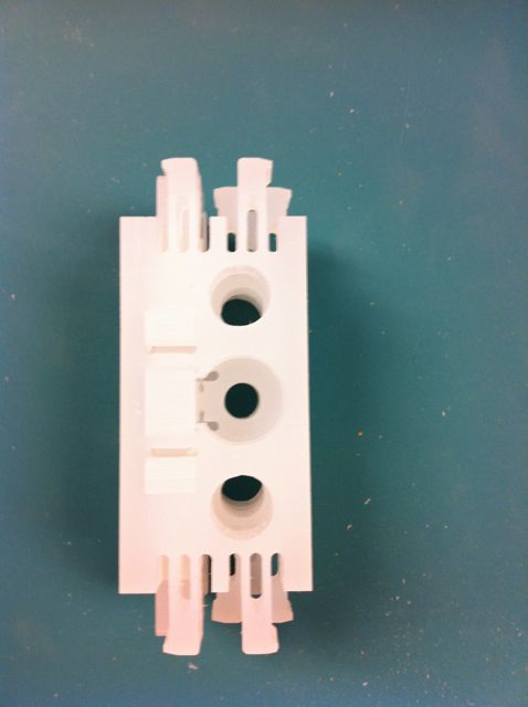
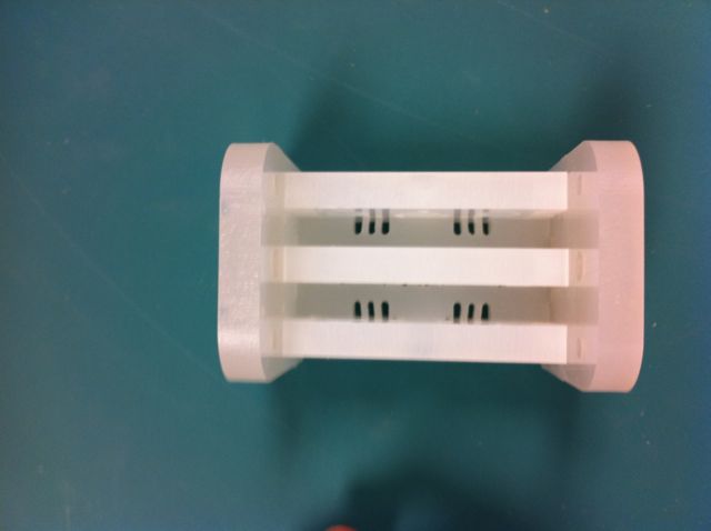
Frame

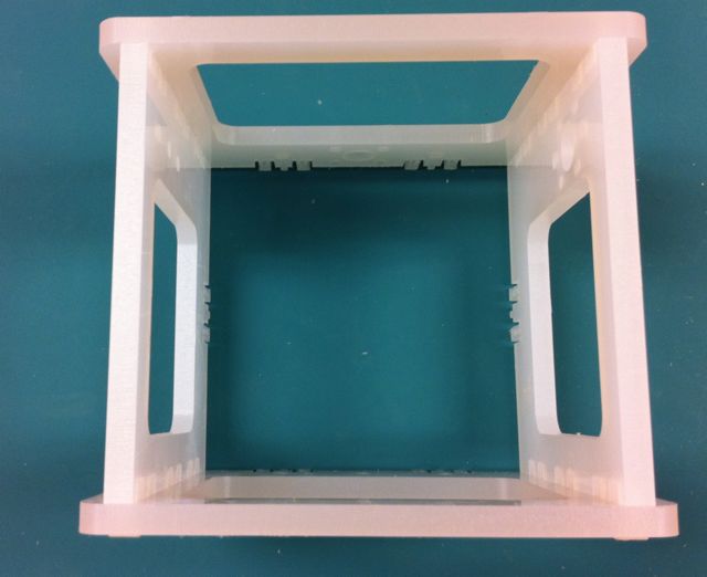
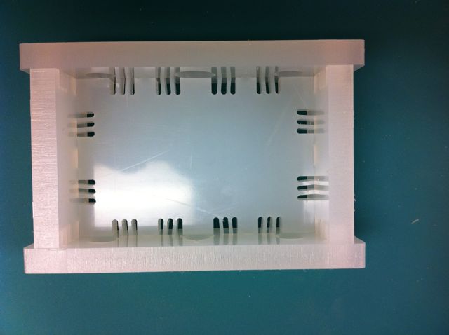
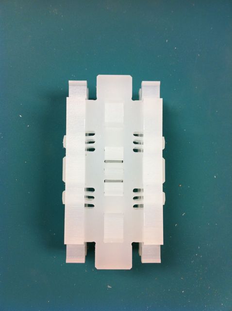
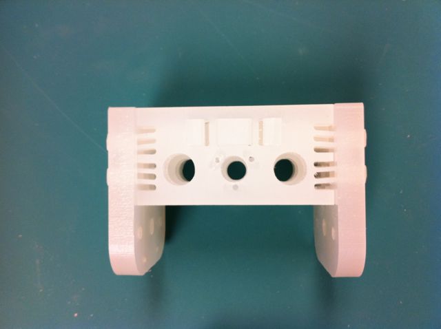
Gantry
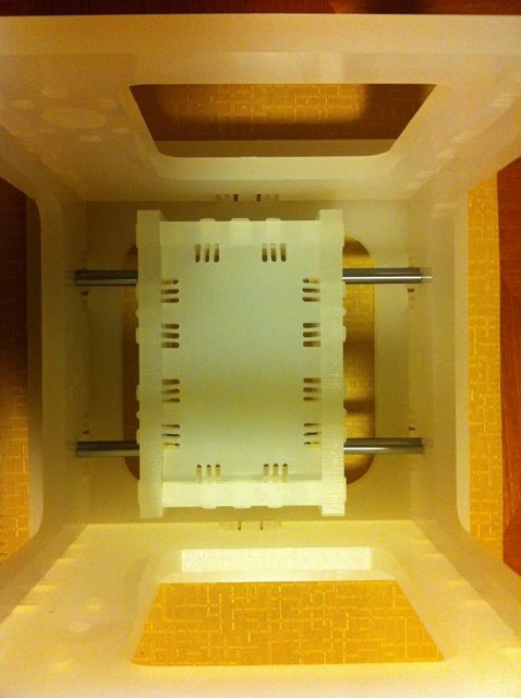
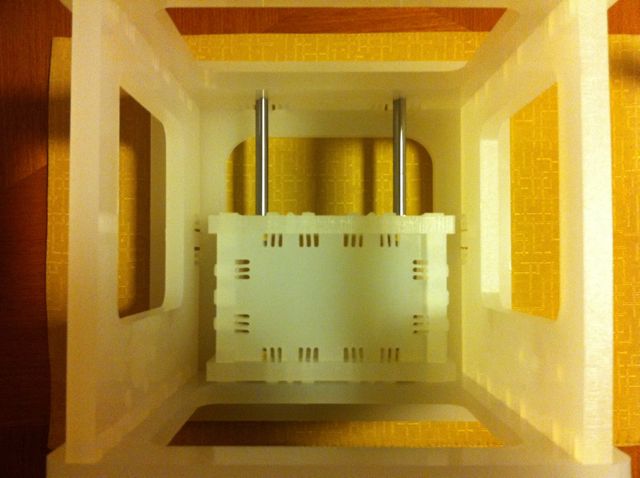
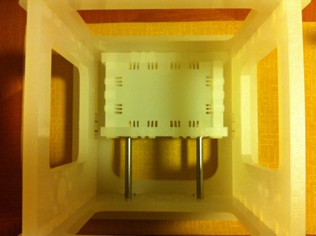
Bushings aligned to slide easily prior to installation on rods in frame.
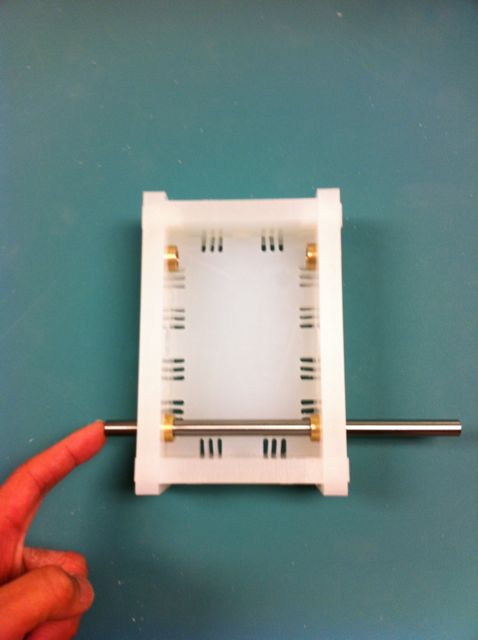
I have some moderate resistance in the front half of the table travel, but none from the rear to about the 2/3 of the wat to the front. I am looking into this currently.
I have fabricated and assembled the basic components and look forward to assembly photos or video and design of control electronics to integrate sub assemblies and integrate motion and motors.
Shopbot file mtm_snap_1-2inch -rot IF FA project.crv.